The Ultimate Guide to Grinding with Spindles: Techniques & Tips

Spindles are at the heart of the modern CNC machine shop operation. They transfer power from the motor to the cutting tool, controlling the cutting direction, speed, and feed. They also deliver lubricant throughout the spindle and cooling fluids to the cutting surface. Today’s spindles can deliver high-speed grinding at more than 250,000 RPM, providing precision and accuracy that were not possible just a few decades ago.
Parts of the Spindle
Every spindle is different, but these are the basic parts:
- Spindle Shaft: The shaft runs the length of the spindle, delivering power from the spindle motor to the cutting tool.
- Spindle Motor: This is often an electric motor that delivers the rotational power that spins the shaft and, ultimately, the tool.
- Bearings: Bearings, consisting of high-grade ball bearings within a set of races, allow the spindle to spin freely in its housing.
- Tool Holder: The tool holder grips the tool, holding it in a precise position for the spindle grinding process.
- Spindle Housing: This is the overall housing of the spindle, encasing the shaft and other system elements. Many spindles include a cooling system, allowing the operator to control the temperature (grinding with spindles often creates high temperatures) and lubrication channels to deliver oil to critical points in the spindle.
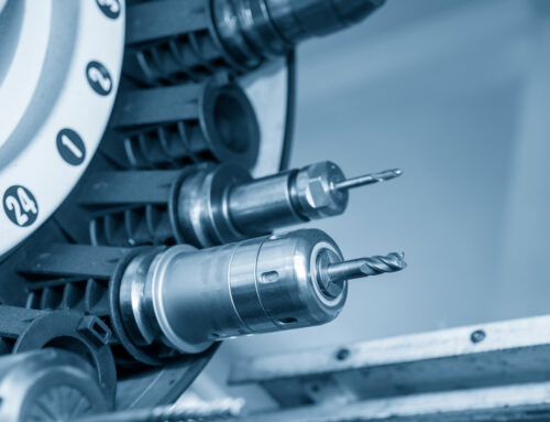
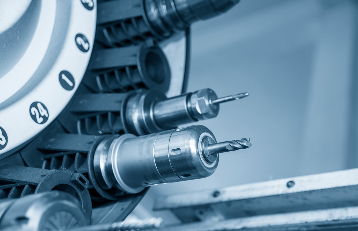
- Automatic Tool Changers: Not every spindle uses automatic tool changers. Many spindles require tools to be changed by hand. However, many spindles allow for this automation. It’s faster and more likely to be error-free.
Let’s Talk About Grinding with Spindles
All spindles grind. They remove material from a rough block of substance, referred to as the workpiece, to achieve a desired form, often with specific detail. That workpiece could be wood, high-grade plastic, or different types of metal. In this article, our conversation refers to various types of metal workpieces.
Spindles enable the high-speed grinding process by delivering a spinning tool to the workpiece, often at high speeds and at precise angles. This is known as subtractive manufacturing because it subtracts or removes material, as opposed to additive manufacturing, which adds material (such as 3D printing).
Types of Spindles
- Belt-Driven Spindles: These spindles use a belt to transfer power from the motor to the spindle. They provide speed but not necessarily a high degree of torque. For some jobs, they are an affordable solution.
- Direct-Drive Spindles: These spindles connect to the motor via a gearbox. There is a more solid connection to the drive source. You get high speeds, more torque, and more precision.
- Spindles with Internal Motors: Some spindles come with an internal motor, And this might be the perfect solution for a particular application.
- Water-Cooled and Air-Cooled: spindles. Many spindles come with an internal cooling system. Water-cooled systems require a separate chiller to cool the water after it removes heat from the spindle. Air-cooled spindles need adequate circulation, which could be problematic if space is at a premium in your factory.
Types of Spindle Grinding
There are different types of spindle grinding. Some examples include:
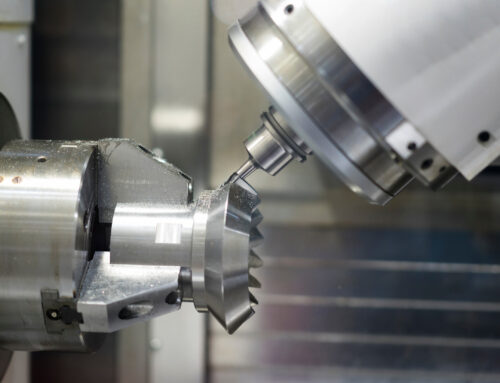
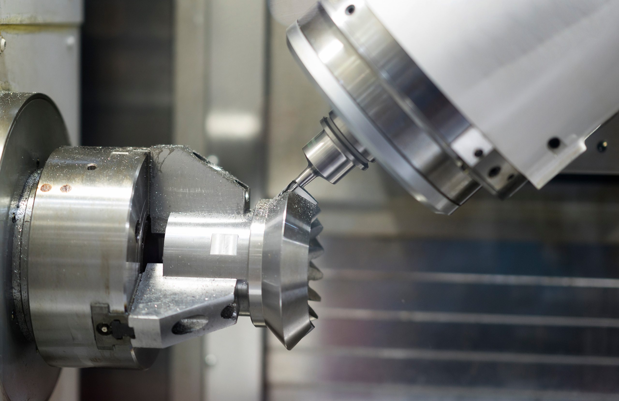
- ID Grinding: ID grinding is the process of grinding an inner diameter of a part. When ID grinding is done it can not be done between centers so typically the part is held in a 4-jaw chuck and is spun at a specific RPM while a high-speed spindle with a grinding wheel attached removes stock. Grinding longer parts, such as a pilot in a shaft, requires a steady rest to bear the overhanging weight and decrease the overall deflection of the part. Another popular method of holding a part for ID grinding is using a magnetic chuck, this setup works best for stubbier parts, for example bearing housings or front caps.
- Thread Grinding: Thread grinding is done when hard parts need threads. Hard parts cannot be threaded by traditional methods like tap and die. Instead, specially shaped grinding wheels are used. The spindle holding the grinding wheel must move in sync with the speed of the rotating part depending on what pitch is needed. For example, a thread with a 1 mm pitch must move 1 mm in the X direction for every 1 rotation of the part. This process is repeated several times, each time the grinding wheel is fed into the part in the Y direction until the threads are deep enough in the part.
- OD Grinding: OD grinding is the process of grinding the outer diameter of a part. This is normally done between precision centers. The part is spun and a spindle with a large grinding wheel removes stock. Using this method, it is possible to hold very tight tolerances. To get the best surface finish on a part, a good practice is to traverse the grinding wheel on the part during the grind. This makes up for any inconsistencies the grinding wheel may have.
- Gear Grinding: Gearboxes are another commonly found item in manufacturing. Gears are machined to a high degree of accuracy to mesh with one another precisely and provide maximum power.
- Tapered Grinding: Some spindle grinding processes need a tapered exterior surface to mate with another part, and this surface often requires a fine finish. Tapered grinding tools are conical-shaped wheels, usually made of aggregate material, with a surface that tapers outwards. They come in different sizes and taper angles, depending on the application.
- Traditional Grinding: Some processes require traditional grinding. There are grinding wheels of different sizes, grains, and bevel angles that operate more efficiently at lower speeds and others at high speeds.
Grinding Tools: The Finish
Any discussion of traditional grinding tools considers the type of finish required on the final workpiece. If you look at the profile of a magnified ground surface (you will have to use a microscopic device), you can see a series of peaks and valleys. The more irregular the peaks and valleys appear and the greater the difference between the highs and lows, the coarser the ground surface is. The more uniform the difference between peaks and valleys, and the less difference, the smoother the ground surface is.
Visually, you can see the difference without a microscope by looking at the surface’s reflective quality. Uniform peaks and valleys reflect light at similar angles, creating a superior reflection (a mirror finish indicates an almost perfect surface). The greater the peaks and valleys, the more irregular the angles of reflected light, and the duller the machined surface will appear. You can sometimes see individual machine marks.
The quality of the ground surface depends greatly on the grinding wheel you use.
The Elements of a Grinding Wheel
The Abrasive Grains
A close examination of a grinding wheel reveals a surface resembling sandpaper. Rather than sand, however, these are tiny, very sharp ceramic grains. Silicon carbide is one type of ceramic used in grinding wheels. In the grinding process, as these ceramic grains dull, they fracture, revealing new sharp surfaces and often entirely new pieces of silicon. In that way, the grinding wheel renews itself.
In some instances, and with some materials, grinding wheels become clogged with bits of metal and swarf lodged in the small spaces between the grains. Operators must remove this build-up and also take off the dull or worn grains, exposing sharper ones underneath, in a procedure known as dressing. Dressing renews the cutting ability of the wheel, ensures quality grinding, and extends the serviceable life of the wheel.
Grinding wheels made of CBN (cubic boron nitride) or natural diamond will eventually lose their effectiveness. When this happens, the wheels require replating by a vendor that specializes in this process. Quality replating vendors will strip each wheel of grinding debris, inspect it for changes in shape or other irregularities, and then revitalize the wheel with an electroplating process. A quality vendor will restore your worn CBN and diamond wheels to the same tolerances as when they were new.
Grit size refers to the size of the individual grains and is measured in the number of pieces of grit per linear inch on the grinding wheel. The larger the grit number, the smaller the grains and the finer the surface.
A measure of grind is the size of the chip removed from a surface. There are ceramic grinding wheels that can remove a chip as small as 0.0002, about the size of a particle of cigarette smoke.
The Bond
The other element of a grinding wheel is the material or cement used to hold the grains together, known as the bond. Like grains, the bond breaks away during grinding, exposing new grains and sharp edges.
Different grinding wheels use different bonds, depending on the project.
- Vitrified: Vitrified bonds use clays and ceramic grains fired in a kiln, forming a glass-like bond. Under pressure, this bond breaks away, revealing new grains.
- Organic Bonds: These bonds consist of organic materials, such as resin. They soften under the heat of grinding, exposing new, sharper surfaces and grains.
- Rubber: Rubber bonds are the softest of the bond material. Grinding wheels with rubber bonds produce a high-quality finish. Rubber wheels are also used with centerless grinding, as they are very effective at minimizing vibration.
Operators use different grain materials and different bonds in spindle grinding. If you are unfamiliar with them, it is best to consult your spindle tool vendor or partner to determine the best solution.
Tips for Selecting the Right Grinding Tool
One of the duties of the spindle operator is selecting the right tool for the spindle grinding process. Your considerations in this selection process should include:
- Type of Material: The type of material you are machining is an important factor. Some metals are harder than others. Some metals distort at higher temperatures generated in the spindle grinding process, while others maintain their integrity.
- The Invasiveness of the Grinding: Some grinding requires the removal of a minimal amount of material, while other processes remove more material at a greater depth. The more invasive the process, the longer the grinding and the greater the temperatures.
- Desired Finish: A water jacket in an engine block does not require the same finish as the polished surface of a valve seat in the same engine block. Different surfaces require different grinding tools.
- Speed: This is an important consideration. The two significant drivers of speed in the spindle grinding process are the need for intricacy (higher speeds enable more accuracy) and production rates. All things being equal, manufacturers tend to lean towards faster production times.
- Type of Tool: Spindles are expensive. They cost tens of thousands of dollars and often more. Experienced operators don’t scrimp when it comes to the tool placed in the end of the spindle. Tool failure can be expensive. Opt for well-designed tools that hold up to thousands of repeated uses.
Tips for Selecting the Right Grinding Tool
There are different types of high-speed grinding.
Surface Grinding
Frequently, the spindle grinding process requires such close tolerances that a process called surface grinding is needed. In other instances, the part may need a smooth, almost mirror-like finish to interact with another component. Using an appropriate grinding tool at the right speed and feed rate allows the machinist to obtain this result.
Internal Grinding
Internal grinding is the process of finishing a hole already created in a piece of metal for a specific application. This is typical for cylinder walls in an automobile engine or hydraulic pump. After the initial hole is machined, the spindle operator repeats the process with a different tool to create a smooth finish. Other applications call for holes drilled and then sized accurately using a specialized tool, like a reamer for example. You will sometimes hear internal grinding referred to as reaming, boring, or honing.
Troubleshooting Common Problems in Grinding with Spindles
There are some common problems you will encounter when grinding with spindles. Some of them, with the right expertise, can be remedied in-house. Others may require the services of the spindle OEM (original equipment manufacturer).
Here are some tips on diagnosing spindle problems.
- Balance issues: The high levels of RPMs encountered in spindle grinding require the spindle to be perfectly balanced. The most frequent indication that there is a balance issue is excessive vibration or noise during operation. Balance issues will usually compromise whatever high-speed grinding process is underway. Stop the operation and examine the spindle. A technician in your factory can make the repairs, or you may need to call a spindle repair facility or the spindle OEM for service. Periodic spindle maintenance should include checking the balance of the spindle.
- A change in grinding quality: A degradation in cutting, drilling, finishing, or any other spindle grinding process might indicate a problem. Immediately check the balance. If the balance appears satisfactory, then inspect the tool holder. The operator may have installed the tool incorrectly, the tool holder may be malfunctioning, or the tool may be reaching the end of its service life.
- Watch temperature levels: Spindle operators should check operating temperatures regularly. Check the cooling system if the temperature falls outside the proper range. You might need to add coolant, change the coolant blend, inspect the cooling system for obstructions, or address any of a number of other issues.
Speed vs. Feed in Spindles
An incorrect balance between speed and feed is another area of spindle grinding that can cause problems.
Speed, often called cutting speed, refers to how fast the outside edge of the tool turns.
Feed, or feed rate, is the speed at which the cutting tool advances along or through the material. For instance, if you are cutting a groove in a piston for seating the seal, the feed rate indicates how fast the tool progresses through the material as the piston rotates.
Most spindle grinding processes have an optimum operating range for speed and feed. If speed and feed are not within that range, the process can generate higher temperatures, damaging the spindle or tool, or distorting the machined material.
- Efficiency: If either speed for feed is out of optimum range, productivity suffers, either by slowing down the process with the need to constantly stop and readjust, or by having a higher rejection rate of finished parts.
- Safety: Overheated tools can fail, resulting in machine failure, the possibility of parts breaking, and injury to employees.
- Surface finish: The optimum feed rate provides the best possible finish for the part.
GMN USA: Your Source for High-Speed Spindles
GMN USA carries a complete line of custom-engineered spindles incorporating the latest technology. GMN USA also provides expert repair services on spindles of all makes and brands, and solutions for monitoring the health of your spindles. GMN USA’s IDEA-4S monitors the performance of your spindle and saves the information in a database for easy access.
Contact GMN USA today to find a perfect match for your high-speed motor needs.

